

Bobcat hydraulic hose diagram shares one shorthand — circled numbers for individual hoses, letters for routing reference points. Once you understand the pattern, a leaking lift or tilt line can be swapped in about 20 minutes instead of turning into guesswork. Coming up, we cover the 641 through T630 family diagrams, show what each number connects to, and identify the wear points that fail first.
How To Read A Bobcat Hydraulic Hose Diagram?
Most Bobcat hydraulic hose diagram layouts use the same visual shorthand. Once you know what the symbols mean, it becomes much easier to trace the circuit from the valve section to the lift arm and then to the tilt cylinder.
Circled numbers identify individual hoses. Dashed lines usually show runs that pass behind the frame, below guards, or along the inside of the lift arm. Letters are routing references. If the same letter appears in two places, it marks the same flow path even when the drawing is broken apart.
Keep these quick rules in mind:
- Rod-end hoses retract the cylinder
- Bore-end hoses extend the cylinder
- Pivot hoses flex through every arm cycle
- Long upper loop hoses often wear at clamp points first
- A wet steel tube often means a hose above it is weeping down
A clear Bobcat hydraulic hose diagram also helps when you are comparing hydraulic hose assemblies and lift cylinder hoses before placing an order.
Hose Positions By Model Series
A Bobcat hydraulic hose diagram is most useful when the model group is separated clearly. The hose layout stays similar in principle, but the number of runs and the routing detail change a lot from older 600 Series machines to later M-Series loaders.
600 Series (641–645)
Models covered: 641, 642, 642B, 643, 645
This is the simplest layout in the group. Four numbered hoses cover the main loader circuit.
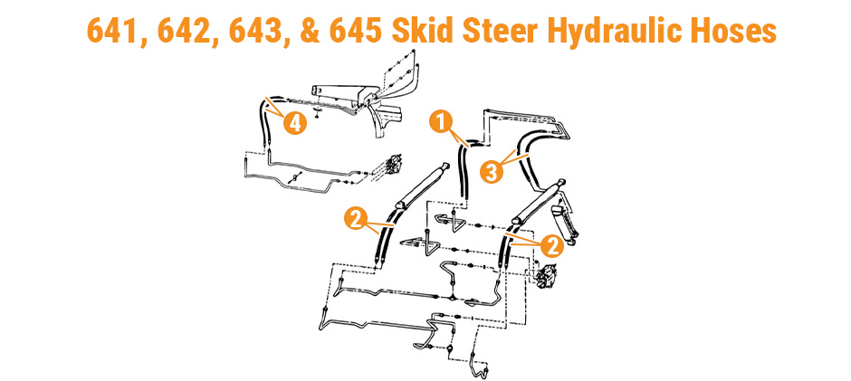
| # | Hose Location |
|---|---|
| 1 | Loader lift cylinders, both sides |
| 2 | At pivot arm, in loader bucket tilt circuit |
| 3 | To loader bucket tilt cylinder, both sides |
| 4 | At pivot arm, in auxiliary function circuit |
On these machines, the pivot-area hoses deserve the closest watch. Hose 2 and hose 4 flex during every work cycle, and they are the most likely to rub on nearby edges. If you are doing scheduled service, this is also a good time to inspect bucket tilt hoses and hydraulic cylinder seals around the same area.
700 Series (753 Group)
Models covered: 753, 753C, 753F, 753G
The 753 group appears in more than one diagram version depending on the serial number. The main layout is:
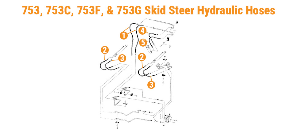
| # | Hose Location |
|---|---|
| 1 | At pivot arm, in bucket tilt circuit |
| 2 | Loader lift cylinders, rod end |
| 3 | Loader lift cylinders, bore end |
| 4 | Bucket tilt cylinder, rod end |
| 5 | Bucket tilt cylinder, bore end |
| 6 | At pivot arm, in auxiliary circuit |
This group is where fitting variation becomes a real parts-order problem. Some machines use one thread size on the lift cylinder hose, while another serial range uses a larger fitting. It is worth measuring both ends with calipers before you buy. When lift speed drops or a cylinder drifts, inspecting the control valve parts and hydraulic fittings around the same circuit can save another teardown later.
800 Series (853)
Models covered: 853
The 853 has a compact hose map with five main positions.
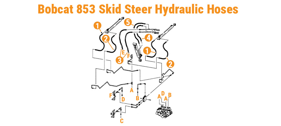
| # | Hose Location |
|---|---|
| 1 | Loader lift cylinders, rod ends |
| 2 | Loader lift cylinders, bore ends |
| 3 | At arm pivot, to bucket tilt cylinder |
| 4 | Bucket tilt cylinder, rod end |
| 5 | Bucket tilt cylinder, bore end |
Hose 3 is the usual wear point on this frame. It wraps the pivot area and sees constant movement. If the outer cover looks polished, cracked, or damp, replace it before it bursts under load. Many shops keep a spare pivot hose and tilt cylinder hose on hand for this model because downtime often starts there.
M-Series Hose Layouts: S550 And T630
This is where many parts orders go wrong. The Bobcat hydraulic hose diagram for the S550 and T630 should not be treated as one shared explanation. The numbering may look similar at first glance, but the image structure is different, and the S550 picture needs extra care.
M-Series: S550
Models covered: S550
The S550 image shows two separate hydraulic layouts in one picture. That is the key point. You are not looking at one continuous diagram. You are looking at a left-side version and a right-side version for different routing arrangements on the same model family.
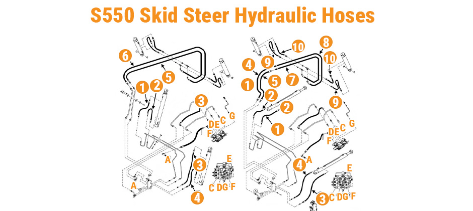
S550 Left-Side Diagram
The left-side drawing is the simpler version. It uses fewer numbered positions and gives a broad view of the main lift and tilt hose runs.
| # | Hose Location |
|---|---|
| 1 | Lift cylinder hose |
| 2 | Upper lift or arm connection hose |
| 3 | Lower main hydraulic hose run |
| 4 | Lower routing hose near valve area |
| 5 | Long upper loop hose across lift arm area |
| 6 | Upper end connection near attachment side |
In this image, hose 5 stands out first. It forms the large loop across the upper arm area and should be checked closely for rub marks, cover wear, and clamp pressure. Hoses 3 and 4 run lower toward the valve area and can collect oil film from leaks above them. If you are replacing these lines, compare them with your lift arm hoses and nearby hose clamps and guards before reassembly.
S550 Right-Side Diagram
The right-side drawing is more detailed. It splits the tilt circuit into more individual hose sections, so the layout expands to ten positions.
| # | Hose Location |
|---|---|
| 1 | Left lift cylinder, rod end |
| 2 | Left lift cylinder, bore end |
| 3 | Right lift cylinder, rod end |
| 4 | Right lift cylinder, bore end |
| 5 | At arm pivot, tilt circuit, rod end |
| 6 | At arm pivot, tilt circuit, bore end |
| 7 | Along lift arm, tilt circuit, rod end |
| 8 | Along lift arm, tilt circuit, bore end |
| 9 | Bucket tilt cylinders, rod ends |
| 10 | Bucket tilt cylinders, bore ends |
This version is better for exact leak tracing. You can separate the problem into three zones:
- Lift cylinder hoses
- Pivot and arm-run hoses
- Tilt cylinder end hoses
That matters because a leak near the loader arm may not mean the cylinder hose itself has failed. It may come from the pivot pair or from the longer arm-run pair. When servicing this area, inspect your bucket cylinder hoses and quick coupler hydraulic parts if the machine also works with hydraulic attachments.
M-Series: T630
Models covered: T630
The T630 diagram is easier to follow because the image presents one main routing layout instead of two side-by-side versions. The hose path is shown more like one continuous system from the lower valve area, through the lift arm, and out to the tilt cylinder ends.
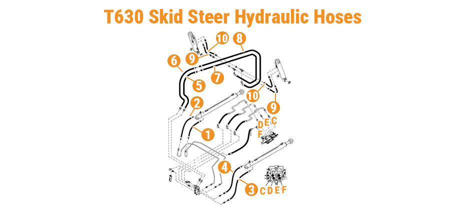
| # | Hose Location |
|---|---|
| 1 | Left lift cylinder, rod end |
| 2 | Left lift cylinder, bore end |
| 3 | Right lift cylinder, rod end |
| 4 | Right lift cylinder, bore end |
| 5 | At arm pivot, tilt circuit, rod end |
| 6 | At arm pivot, tilt circuit, bore end |
| 7 | Along lift arm, tilt circuit, rod end |
| 8 | Along lift arm, tilt circuit, bore end |
| 9 | Bucket tilt cylinders, rod ends |
| 10 | Bucket tilt cylinders, bore ends |
The top of the image highlights the long upper runs. The middle section shows the transition through the pivot area. The lower section leads back to the valve and machine-side supply. That makes the Bobcat hydraulic hose diagram for the T630 especially useful during troubleshooting because you can isolate the circuit by function.
A quick way to narrow the fault:
- Slow lift or drift points first to hoses 1 through 4
- Curl or dump issues point first to hoses 5 through 10
- Oil around the upper arm should lead you first to hoses 7 and 8
- Oil at the attachment end should send you to hoses 9 and 10
Because the T630 is a track loader, routing stability matters even more. Vibration and frame movement can shorten hose life if the line twists during installation. Matching the original path with proper hydraulic line supports and protective hose sleeves helps prevent early failure.
Replacement Checklist And Failure Signs
A Bobcat hydraulic hose diagram tells you where the hose goes. It does not guarantee the replacement hose is correct. Before you pull the old line, gather the fitment details that usually decide whether the repair goes smoothly or stalls.
What To Check Before Ordering?
Use this checklist:
- Write down the full model and serial number
- Match the machine to the correct diagram version
- Measure both fitting ends
- Measure hose length from sealing face to sealing face
- Note routing clips, bend direction, and protective wrap
- Confirm pressure rating matches the original circuit
- Check whether the leak is actually from the hose, not the fitting or cylinder port
It is also smart to inspect nearby seal kits, hydraulic adapters, and tube clamps while access is open.
Common Failure Signs
Most hose failures start with visible surface clues before the line bursts.
Watch for:
- Cover cracks near the pivot
- Wet or dusty oil film along the hose body
- Bulges near the crimp
- Flattened or kinked sections
- Chafing where the hose crosses metal edges
- Sluggish lift or tilt caused by inner liner collapse
A steel tube that looks wet often misleads people. In many cases, the actual leak is the rubber hose above it, with oil running downward along the frame.
Installation Habits That Prevent Repeat Leaks
After you install the new hose:
- Clean both ports and threads
- Lightly oil O-rings if used on that fitting style
- Tighten to the correct torque
- Route the hose in its natural curve
- Cycle lift and curl functions at low idle
- Recheck for seepage after pressure comes up
Do not force a twist out of the hose after both ends are tight. That often turns into a fresh leak within days. If the hose does not sit naturally, loosen one end and re-clock it before final torque.
Final Words
A clear Bobcat hydraulic hose diagram turns a messy repair into a straight parts order. Match the number to your cylinder end, confirm the S/N range, and check thread size before you buy. For replacement lift, tilt, pivot, and auxiliary hoses across the 641 through T630 skid steer lines, we stock affordable aftermarket options at FridayParts with wide compatibility across Bobcat and other heavy equipment brands, so you can get back to work.
