

The wiring layout is similar across most Cub Cadet solenoids. One large terminal takes power from the battery, another sends it to the starter, and a small terminal gets the ignition signal. Some solenoids have a separate ground terminal. Model-to-model routing differs, so check the Cub Cadet starter solenoid wiring diagram below to make sure your wiring is correct.
Starter Solenoid Terminal Layout
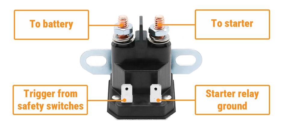
Before looking at a model-specific Cub Cadet starter solenoid wiring diagram, identify the four main connection points on the solenoid.
- To battery – This terminal connects to the battery positive cable.
- To starter – This terminal connects to the starter motor cable.
- Trigger from safety switches – This small terminal receives the start signal after it passes through the ignition switch and safety interlock circuit.
- Starter relay ground – This terminal or ground point completes the control circuit for solenoids that require a separate ground.
Not every solenoid is built exactly the same. Some ground through the mounting bracket or case, while others use a dedicated ground terminal.
Before moving any wires, check the following:
- Terminal count
- Terminal markings
- Mounting style
- Ground method
- Cable position
If the wiring looks old, repaired, or corroded, inspect the battery cable, starter cable, ignition switch, and wire connector at the same time.
Cub Cadet Model Wiring Diagrams
The solenoid serves the same basic purpose on every Cub Cadet machine, but the wiring layout can differ from one series to another.
LT Series: LT1042 Starter Solenoid Wiring Diagram
On the LT1042, the wiring path is usually:
- Battery positive to the large solenoid input terminal
- Solenoid output terminal to the starter motor
- Ignition switch and safety circuit to the trigger terminal
- Battery negative to engine or frame ground
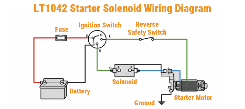
If the engine does not crank, check whether the trigger terminal gets voltage when the key is turned to START. If there is no voltage there, the problem is often in the ignition switch or safety circuit.
3000 Series: 3204 Starter Solenoid Wiring Diagram
The 3204 often has a more direct-looking wiring layout, but older machines commonly have modified wiring, corroded terminals, or repaired harnesses.
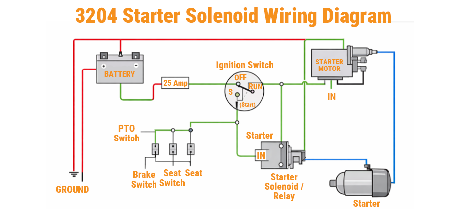
When checking this setup, pay close attention to:
- Battery cable condition
- Ground connection quality
- Harness repairs
- Loose or oxidized terminals
If power is present at the large input post but the starter does not engage, test the trigger wire while the key is held in START.
82 Series: 582 Starter Solenoid Wiring Diagram
The 582 follows the same basic solenoid pattern, but wire routing and switch layout may differ from other Cub Cadet tractors.
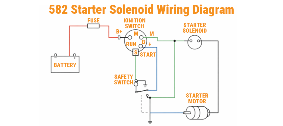
Use the diagram to confirm:
- Battery cable location
- Starter cable location
- Trigger wire position
- Ground connection type
A weak ground can cause the same symptom as a bad starter solenoid, so it is worth checking the ground cable and mounting area before replacing parts.
RZT Series: RZT50 Starter Solenoid Wiring Diagram
On the RZT 50, the heavy cable side is usually simple, but the trigger side often passes through more safety switches.
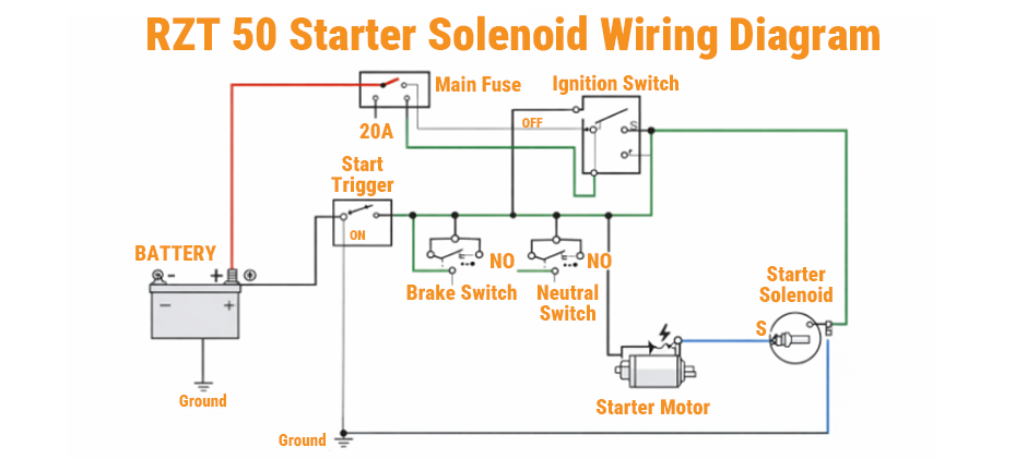
These may include:
- PTO switch
- Park brake switch
- Lever position switch
- Seat switch
If the mower has battery power but does not click or crank, start by tracing the trigger circuit. On many RZT models, the issue is somewhere in the safety interlock path rather than the main battery cable.
GT Series: GT1554 Starter Solenoid Wiring Diagram
The GT1554 uses a familiar garden tractor layout, but the terminal positions and safety switch routing should still be checked carefully.
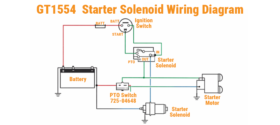
Look for these points:
- Battery positive on one large post
- Starter cable on the opposite large post
- Trigger wire on the small start terminal
- Good ground between the battery negative cable and the engine
If the solenoid clicks but the engine does not turn, measure voltage at both large terminals during START to see whether power is actually reaching the starter motor.
What These Diagrams Have in Common
Most Cub Cadet starter solenoid wiring diagram layouts follow the same general electrical flow.
| Circuit Section | Main Function | Typical Parts |
|---|---|---|
| Power feed | Sends battery power to the starter | Battery, fuse, solenoid, starter motor |
| Trigger path | Activates the solenoid | Ignition switch, safety switches, trigger wire |
| Ground path | Completes the circuit | Battery negative cable, frame ground, engine ground |
When reading a diagram, trace the wiring in this order:
- Battery
- Solenoid input terminal
- Solenoid output terminal
- Starter motor
- Trigger wire
- Safety switches
- Ground path
Following this order makes it easier to tell whether the no-start problem is on the power side or the control side.
No-Start Checks After Matching the Diagram
After finding the closest Cub Cadet starter solenoid wiring diagram, test the circuit before replacing anything.
Basic Checks
- Measure battery voltage with the key off
- Check for voltage at the battery-side large terminal
- Check for voltage at the trigger terminal while holding the key in START
- Check for voltage at the starter-side large terminal during START
- Check ground continuity to the frame or engine
Symptom Guide
| Symptom | Likely Cause | First Check |
|---|---|---|
| No click, no crank | Open trigger circuit | Test trigger terminal voltage |
| Single click, no crank | Weak battery or bad solenoid contacts | Test output voltage and battery condition |
| Repeated clicking | Low battery or poor connection | Clean terminals and charge the battery |
| Starts when jumped | Solenoid or trigger-circuit fault | Compare trigger and output readings |
| Intermittent crank | Loose connector or switch issue | Inspect harness and switch connections |
Common Wiring Mistakes During Replacement
A new solenoid will not solve the problem if the wires are connected to the wrong terminals.
Avoid these common mistakes:
- Connecting the trigger wire to the wrong small terminal
- Reversing the battery cable and starter cable
- Missing the required ground connection
- Reusing damaged terminals
- Installing a similar-looking solenoid with a different terminal layout
Before finishing the job, compare the old and new parts carefully and recheck the battery terminal, starter cable, ignition switch, and safety switch connections.
Final Words
Once you understand the terminal layout, a Cub Cadet starter solenoid wiring diagram becomes much easier to follow. Matching the wiring to the correct model can save time and help you find no-start problems faster. If you need a replacement solenoid or related parts, FridayParts is a practical option for affordable aftermarket parts and broad equipment compatibility.
