

Was cleaning your carburetor and two linkages came off? Don’t worry. This guide walks you through the Cub Cadet throttle linkage diagram, telling you how to connect the engine controls.
What Is A Cub Cadet Throttle Linkage?
On your Cub Cadet riding mowers, the throttle linkage is a crucial mechanism that controls your engine speed. It connects the metal rods and springs that link your throttle lever or throttle cable to the engine’s carburetor and governor system. When you pull the throttle lever, the throttle cable moves and pulls the engine control bracket. Then, the throttle linkage rod transfers this movement directly to the carburetor’s throttle butterfly valve to regulate fuel and air intake. As a result, the linkage springs work with the engine’s governor, which automatically adjusts the linkage to keep the engine running at a steady speed.
Key Components of the System
A Cub Cadet throttle linkage setup basically consists of the following:
- Linkage Rod: A thin metal rod with “Z-bends” or clips on both ends that physically pulls the carburetor lever.
- Governor/Linkage Springs: These maintain tension on the rod, prevent the throttle from fluttering, and help the governor stabilize engine speed.
- Choke Linkage: On many Cub Cadet models, pushing the throttle lever all the way up engages the choke. The linkage ensures the choke plate closes properly for cold starts.
Below is a diagram of the parts on a typical Cub Cadet engine control. 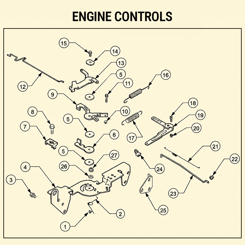
| No. and Parts | No. and Parts | No. and Parts | No. and Parts | No. and Parts | No. and Parts |
|---|---|---|---|---|---|
| 1 Nut, Hex Lock M5 x 0.8 | 6 Lever, Throttle Actuator | 11 Screw, Hex Cap M4 x 0.7 x 30 | 16 Spring, Throttle Limiter | 21 Spring, Linkage | 26 Washer |
| 2 Spring, Choke Return | 7 Clamp, Cable | 12 Linkage, Choke | 17 Spring, Governor | 22 Bushing, Linkage Retaining | 27 Nut, Hex |
| 3 Screw, Hex Flange M6 x 1.0 x 16 | 8 Screw, Hex Flange M5 x 0.8 x 16 | 13Lever, Choke Nut, Hex M4 x 0.7 | 18 Screw, Round Hd. Square Neck | 23 Linkage Throttle | – |
| 4 Bracket, Control | 9 Lever, Throttle Control | 14 Washer, Spring 1/4” | 19 Lever, Governor | 24 Bushing, Linkage Retaining | – |
| 5 Washer, Plain 5.5mm | 10 Nut, Hex M4 x 0.7 | 15 Screw, Hex Flange M5 x 0.8 x 20 | 20 Nut, Hex Flange M6 x 1.0 | 25 Bracket Support | – |
Cub Cadet Throttle Linkage Diagram Explained
Here is a throttle linkage diagram for the Kohler Command 18 Engine in Cub Cadet 2186.
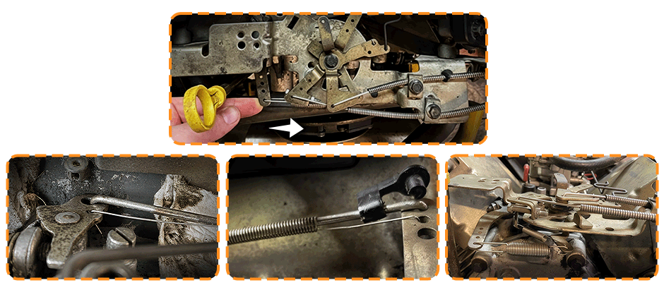
To help you better understand it, look at the picture and follow the steps below.
How to Connect the Engine Controls?
To help you better understand it, look at the picture and follow the steps below. 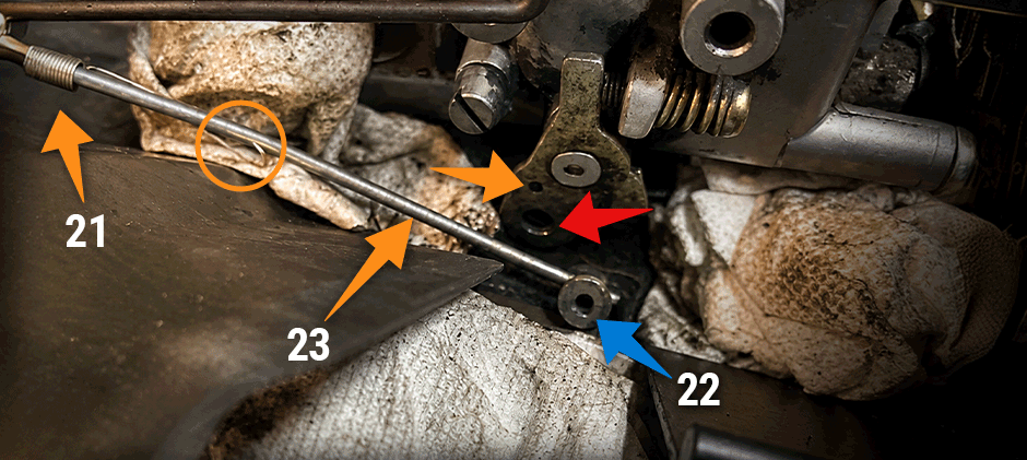
- First, you must find the grouped parts #21(spring), #22 (bushing) and #23 (throttle linkage).
- The end of #21(orange cycle) should go into the small hole (orange arrow)
- The #22 bushing should fit into the larger hole in the throttle (marked with red arrow)
- The #23 rod should be pressed through after putting the bushing in.
- The end of the #23 rod should be able to slide back and forth in the #22 bushing while the #21 spring keeps it at the end.
Common Signs of An Improperly Adjusted Throttle Linkage
The throttle linkage is a critical component of your Cub Cadet engine, as it plays a key role in controlling the engine’s speed and power output. Once the throttle linkage is malfunctioning or improperly adjusted, you may encounter the following problems:
- Decreased fuel economy
- Poor acceleration
- Engine stalling
Wrapping up
Understanding the Cub Cadet throttle linkage diagram can help save you from downtime and costly maintenance and repairs. You can learn more about the carburetor diagram in our blog posts. At FridayParts, you can source a wide range of lawn mower carburetors and carburetor parts to keep your Cub Cadet mowers running like new.
You Might Also Like
Briggs & Stratton Throttle Linkage Diagram: A Complete Guide
John Deere Throttle Linkage Diagram: A Complete Guide
Kohler Carburetor Linkage: Throttle Linkage Diagram Explained
