

The right Ford tractor ignition switch wiring diagram depends on the series, voltage setup, and terminal arrangement. That’s the root of so many wiring errors after Ford tractor repairs. Match your tractor correctly first. Use the diagrams and terminal chart below before attaching any wires. It’s a quick check that prevents a no-start headache down the road.

Ford Tractor Ignition Switch Wiring Diagram
Before tracing wires, match your tractor to the correct Ford tractor ignition switch wiring diagram and compare the switch terminals with the chart below.
Switch Terminal Chart
| Terminal Marking | Circuit Job | Common Connection Point | What It Powers |
|---|---|---|---|
| B | Battery feed in | Battery side of solenoid or regulator battery feed | Main power into switch |
| IGN | Ignition feed out | Coil input side | Spark system in run position |
| A | Accessory or run feed | Gauges, warning lights, fused dash feed | Dash and ignition-related circuits |
| S | Start signal out | Safety starter switch or starter solenoid control terminal | Cranking circuit |
| ACC | Accessory feed | Lights or optional electrical circuits | Non-start accessories |
| G | Ground or special function on some models | Ground path or model-specific circuit | Depends on tractor setup |
Wire colors may not tell the truth on an older tractor. A clean terminal map is more useful than guessing by faded insulation. While checking the switch, inspect nearby ignition switches, starter solenoids, and wiring harness parts for heat damage, corrosion, or loose connectors.
9N And 2N Diagram
For 9N and 2N tractors, the Ford tractor ignition switch wiring diagram is usually simple, but many tractors in this group have been converted from 6 volt to 12 volt. That changes more than charging parts. It can also change coil feed routing and resistor use.
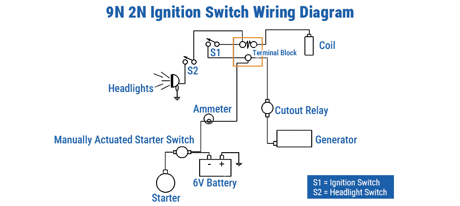
Check these points first:
- original 6-volt or converted 12-volt
- current charging system type
- resistor setup
- coil feed path
If the tractor still uses older charging hardware, inspect generator parts, voltage regulators, and battery cables at the same time.
8N 6 Volt Diagram
If your 8N hasn’t been converted from 6 volts, stay with the 6-volt diagram. A 12-volt layout will only cause wrong routing and more time spent diagnosing.
Use this diagram when the tractor has:
- original 6-volt charging system
- original-style ignition feed
- matching resistor and coil setup
Early 8N Diagram: Early 8N tractors need the correct diagram by serial range. Using a late 8N layout on an early tractor can send you in the wrong direction fast.
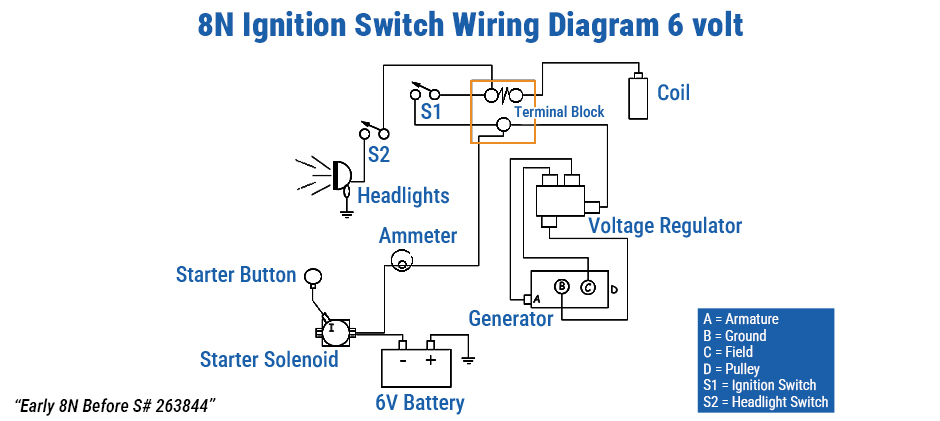
Use this diagram for:
- Early 8N before serial number 263844
- Original 6-volt system if unchanged
- Correct early ignition layout
On these tractors, the ignition switch circuit is closely tied to the rest of the ignition path. If it still won’t fire after rewiring, check tune-up parts and spark plug wires too.
Late 8N Diagram: Late 8N tractors use a different layout, so they should not be grouped together with early models. This is one of the most common causes of wiring mistakes.
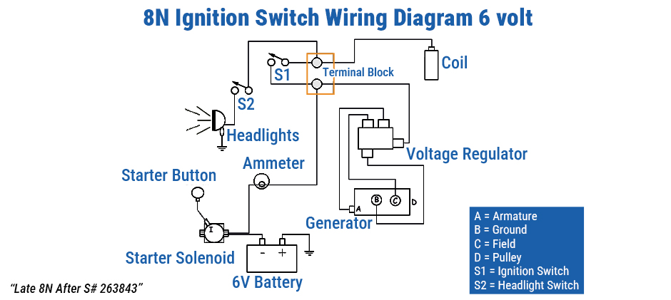
Use this diagram for:
- Late 8N after serial number 263843
- Correct late-series ignition routing
- Current charging system setup
On a converted tractor, don’t trust memory. Compare the current circuit with the switch diagram. Older tractors often have mismatched parts and patched wiring. Clean connectors and use quality ignition components.
8N 12 Volt Diagram
A converted 8N should have its own Ford tractor ignition switch wiring diagram. A 12-volt conversion usually changes the charging side, resistor configuration, and sometimes the coil feed.
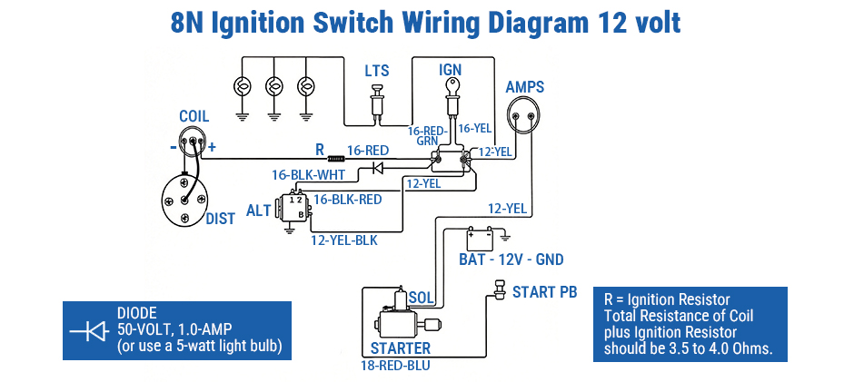
Use this diagram when the tractor has:
- 12-volt battery system
- alternator conversion
- modified ignition feed layout
Before startup, inspect alternators, charging wires, and coil wiring parts so the switch circuit matches the converted system.
A good match here can save time. It also helps to check voltage regulators, battery terminals, and ground straps before blaming the switch.
601 And 801 Diagram
The Ford tractor ignition switch wiring diagram for 601 and 801 tractors usually shows a more developed run and start circuit than the earlier N-series tractors.
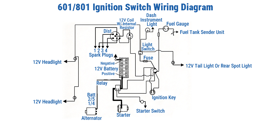
You will usually see:
- battery feed into the switch
- ignition feed out in run
- start output to the crank circuit
- accessory or lamp terminals on some machines
Some tractors in this group now have alternator conversions or updated harness sections. In those cases, inspect switch connectors, dash harnesses, and charging system parts carefully.
2000 Series Diagram
Ford 2000 tractors look similar but differ underneath. The correct Ford tractor ignition switch wiring diagram hinges on the engine configuration, fuel type, and whether the original switch is still installed.
Confirm these items first:
- 3-cylinder or 4-cylinder
- gas or diesel
- number of active switch terminals
- lettered or numbered switch markings
- original or modified harness
Some 2000 series tractors use extra terminals for lights or horn circuits. A replacement switch may also have more blades than the harness actually uses. Match wires by function, not by blade count alone.
How The Switch Works
With the correct Ford tractor ignition switch wiring diagram in hand, work through the switch by key position. That’s the simplest way to understand the circuit.
Off Position
In the off position, the ignition circuit should lose power. On a gas tractor, the coil should not stay live. If the engine keeps running after you turn the key off, the ignition wire is likely on the wrong terminal.
Run Position
In the run position, battery power passes through the switch to the ignition circuit. This often includes:
- ignition coil
- warning lights
- gauges
- voltage stabilizer on some tractors
If the tractor cranks but has no spark, this is the first circuit to test. A weak ignition coil or worn fuse holders can create the same symptom.
Start Position
In the start position, the switch sends power to the crank circuit. That path often runs through a safety switch before it reaches the starter solenoid.
Basic start path:
- Battery feed enters the key switch
- Key turns to start
- Start terminal sends voltage out
- Safety switch passes the signal
- Solenoid engages the starter
If nothing happens at the key, check the starter switch, wire terminals, and solenoid control path before replacing larger parts.
Test Before Startup
After wiring the switch, test the circuit before trying to start the tractor. That extra check can save a second teardown.
Quick Electrical Checks
Use a multimeter or test light to verify:
- battery voltage at B
- voltage at IGN or A in run
- voltage at S in start
- continuity through the safety circuit
- clean grounds at battery and frame
Also inspect for:
- melted insulation
- taped splices
- loose crimp ends
- overheated connectors
- worn fuse links
Fresh battery terminals, clean ground straps, and secure wire terminals often solve problems quickly.
Common Wiring Mistakes
These mistakes show up again and again:
- using the wrong series diagram
- mixing 6-volt and 12-volt wiring
- wiring a diesel switch like a gas switch
- putting coil feed on the start terminal
- assuming every blade on the replacement switch must be used
- ignoring the safety start circuit
A tractor that only runs while the key is held over usually has a misplaced run circuit. If it cranks but never fires, go back over the ignition feed and the starter circuit parts around it.
Final Words
With the right diagram, ignition switch wiring is usually easy. Using the wrong diagram is what causes trouble. Verify the series, confirm the terminals, and test the circuit before startup. When worn electrical parts need replacing, FridayParts provides aftermarket tractor parts without unnecessary cost.
Also Read:
