

A Husqvarna ignition switch wiring diagram typically has a few key terminals. B is the battery, S goes to the starter solenoid, and M controls the kill function. Additional terminals may be used for lights, accessories, or ground. If the mower won’t crank, cranks without spark, or blows a fuse after a new switch, the switch is probably not the real problem. Most owners don’t realize this, but a Husqvarna ignition switch works the opposite of a car switch. It doesn’t send power to the engine. It kills the spark by grounding it. Test it like a car switch, and you will be chasing the wrong problem for hours. This guide shows you exactly which terminals to test and where the real faults usually hide.
Common Husqvarna Ignition Switch Terminals
A Husqvarna key switch may have 5, 6, or 7 terminals depending on the machine. The terminal letters matter more than the plug’s shape.
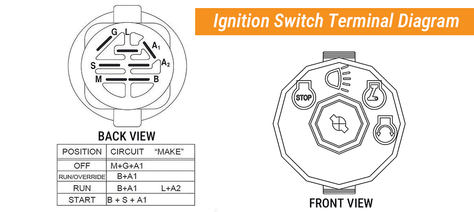
What B, S, M, L, A, and G Usually Mean
| Terminal | Function | Typical Circuit Role |
|---|---|---|
| B | Battery | Constant 12V feed from battery through main fuse |
| S | Start | Sends power to the starter solenoid or start relay |
| M | Magneto | Connects to the kill wire for engine shutdown |
| L | Lights | Feeds the lighting circuit on some machines |
| A | Accessory | Powers hour meter, fuel solenoid, or accessory circuit |
| G | Ground | Ground reference on some switch designs |
The ignition switch connects different terminals at different key positions. That is why the correct part matters. Two switches may look the same but work very differently inside.
An incorrect ignition switch connector layout can lead to no-crank, no-spark, or blown-fuse problems, even when the switch body seems to fit.
How Does The Husqvarna Ignition Switch Circuit Work?
A Husqvarna ignition switch wiring diagram makes more sense when each key position is tied to a circuit function.
OFF Position
In OFF, the engine shutoff path is active.
Typical results:
- Battery feed stays present at B
- Start output stays open
- M terminal may connect to ground
- The kill wire stops the spark
If the M circuit stays grounded all the time, the engine may crank but not start.
RUN Position
In RUN, the engine is allowed to operate, and some powered items may receive voltage.
Typical results:
- B may feed A or L
- The hour meter may power up
- The fuel shutoff solenoid may receive power
- The kill path is no longer grounded
If there is no dash power in RUN, begin with the battery feed, fuse, and switch input.
START Position
In START, the key switch sends power to the cranking side of the system.
The path often looks like this:
- Battery voltage enters the B terminal
- The switch sends power to S
- Power passes through one or more safety switches
- The starter relay or starter solenoid energizes
- The starter motor cranks the engine
On many models, the switch does not power the starter motor directly. It only triggers the control side of the circuit.
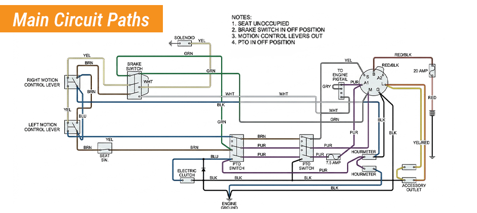
Main Circuit Paths And Safety Switches
A Husqvarna ignition switch wiring diagram usually includes more than the switch itself. The start path, kill path, and safety interlock path all affect whether the machine starts and runs.
Starting Circuit Path
The starting circuit often follows this order:
- Battery
- Main fuse holder
- B terminal on the key switch
- S terminal in START
- Safety switch path
- Starter relay or starter solenoid
- Starter motor
If there is no click when the key turns, the fault is often in this control path.
Kill Circuit Path
The kill circuit normally includes:
- Engine ignition module or magneto
- Kill wire
- M terminal on the ignition switch
- Ground path is OFF
If this wire is pinched or miswired during harness repair, the engine may crank and still have no spark.
Accessory And Lighting Path
Depending on the model, power in RUN may also go to:
- Hour meter
- Fuel shutoff solenoid
- Lights
- Other accessory circuits
This is why a mower may crank but still fail to stay running if the fuel solenoid never gets power.
Safety Switches That Often Interrupt The Start Circuit
Several switches can stop cranking even when the key switch is working.
The most common ones are:
- PTO switch
- Brake switch
- Seat switch
- Clutch switch on some tractor layouts
- Reverse safety logic on some models
Typical signs of a safety switch issue include:
- No click at all
- The machine starts only with controls held in an exact position
- Intermittent starting
- New switch installed, but the problem stays the same
On zero-turns, the control lever position may also affect the start path. On riding tractors, brake or clutch input is more common.
How To Identify And Test The Wires?
If the plug is damaged or the wire colors are hard to trust, wire function matters more than wire color.
Find The Battery Feed
Use a multimeter on DC volts.
Steps:
- Put the black lead on a clean chassis ground or ground cable
- Probe each switch wire with the red lead
- Look for constant battery voltage with the key OFF
- That wire usually belongs on B
If no wire has battery voltage, check the battery, the battery cable, and the main fuse holder first.
Find The Start Wire
The start wire usually leads toward the starter relay or starter solenoid.
To identify it:
- Turn the key to START
- Probe the suspected wire
- Look for voltage only in START
- Trace it toward the small trigger terminal if needed
Find The Kill Wire
The kill wire usually heads toward the engine side of the wiring harness.
Common clues:
- It is part of the spark shutoff circuit
- It should be grounded in OFF through the switch
- A wrong connection here can cause a crank with no spark
Find Light Or Accessory Wires
Accessory wires usually have power in RUN.
They may feed:
- Hour meter
- Fuel shutoff solenoid
- Lighting circuit
Test The Switch With A Multimeter
Testing the switch before replacing it can save time and money.
Voltage Checks
With the switch connected:
- B should have battery voltage at all times
- S should have voltage only in START
- A or L should have voltage in RUN if used on that model
If B has no power, the switch may not be the problem.
Continuity Checks By Key Position
Disconnect the switch before continuity testing.
| Key Position | Likely Closed Contacts | Likely Open Contacts |
|---|---|---|
| OFF | M to G or M to ground path | B to S |
| RUN | B to A or B to L | B to S |
| START | B to S and sometimes B to A | M to ground path |
Use the markings on the switch body if they are still readable. A replacement part can have the same number of terminals but a different internal pattern.
Common No-Start Problems And Fast Checks
Many starting problems tied to a Husqvarna ignition switch wiring diagram can be narrowed down quickly with a few checks.
| Symptom | Most Likely Area | First Check |
|---|---|---|
| No dash power | Battery feed or fuse | Battery voltage and main fuse holder |
| No click when the key turns | S circuit or safety path | Voltage at S in START |
| Clicks but does not crank | High current path | Battery cable and solenoid output |
| Cranks but no spark | M terminal kill circuit | Kill wire grounding in OFF and RUN |
| Runs only with jump wire | Switch output or connector | B and A voltage in RUN |
| Fuse blows after switch swap | Wrong switch or short | Terminal mapping and connector condition |
No Click When The Key Turns
Check these items first:
- Battery voltage under load
- B terminal power
- S terminal power in START
- PTO switch
- Seat switch
- Brake switch
No click usually means the start command is not reaching the relay or solenoid.
Clicks But Does Not Crank
If the solenoid clicks, shift attention to the heavier current side:
- Battery cable
- Ground connection
- Solenoid output
- Starter motor
Cranks But Has No Spark
This often points to the kill side of the system.
Inspect:
- M terminal wiring
- Engine-side lead
- Rubbed section of the wiring harness
- Replacement ignition switch pinout
Fuse Blows After Switch Replacement
This often means one of two things:
- The replacement switch has the wrong internal contact pattern
- One wire is in the wrong position in the ignition switch connector
Before replacing the switch, it also helps to:
- Match terminal letters, not just plug shape
- Inspect the wiring harness for rubbed insulation
- Check the starter solenoid
- Verify the PTO switch and seat switch
Final Words
A Husqvarna ignition switch wiring diagram is most useful when it helps track power, identify each wire, and narrow down faults step by step. If replacement parts are needed, FridayParts offers aftermarket parts, high-quality products at affordable prices, a vast inventory, and wide compatibility for many heavy equipment brands.
