

Looking for a usable Kawasaki starter solenoid wiring diagram? Start simple. B goes to the battery positive, M goes to the starter, and S takes the start signal. The real task is telling the heavy power wires from the control wires and knowing where the circuit can fail. This article walks through it step by step, then applies it to the Bayou 220 and KZ550.
Starter Solenoid Terminal Layout
Before tracing any Kawasaki starter solenoid wiring diagram, identify the terminals on the relay body. This prevents the most common wiring mistake: mixing up the battery cable, starter cable, and trigger wire.
Most Kawasaki starter solenoids use two large studs and one small trigger terminal. The large studs handle current flow from the battery to the starter. The smaller terminal activates the relay coil. Some units ground through the case. Others need a separate ground lead. When installing a starter solenoid, starter relay, or main fuse holder, always confirm how the ground path is completed.
Quick Terminal Reference
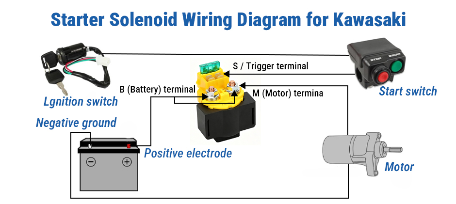
| Terminal | Job | Typical Connection |
|---|---|---|
| B | Battery feed | Battery positive |
| M | Starter output | Starter motor |
| S | Start signal | Start switch circuit |
| G | Ground | Chassis or ground lead |
That covers the relay body itself. Next comes the full Kawasaki starter solenoid wiring diagram, which matters just as much as the terminal labels.
Kawasaki Starter Solenoid Wiring Diagram
A Kawasaki starter solenoid wiring diagram makes more sense when it is split into two parts:
- High-Current Circuit
- Control Circuit
This is the best way to read a Kawasaki starter relay wiring diagram or a starter solenoid wiring diagram on an ATV or motorcycle. It also helps when checking related parts such as a battery cable, ignition switch, starter button, or starter motor.
High-Current Circuit
The high-current side is the power path that turns the engine.
The usual path is:
- Battery positive
- Main fuse
- B terminal on the starter solenoid
- Internal relay contact
- M terminal
- Starter motor
This side uses heavy cables because the starter motor needs high current. If the relay clicks but the engine does not crank, the fault is often here.
Common High-Current Problems
- Weak battery
- Loose battery terminal
- Corroded cable end
- Burned solenoid contact
- Damaged starter cable
- Bad starter motor connection
A worn battery cable, loose starter motor cable, or weak main fuse assembly can stop cranking even when the relay still clicks.
Control Circuit
The control side tells the solenoid when to close.
The usual path includes:
- Battery- or ignition-fed power
- Ignition switch
- Engine stop switch ,if fitted
- Starter button
- Neutral switch, clutch switch, or brake switch
- S terminal on the solenoid
When the start command reaches the S terminal, the relay coil energizes. That pulls the internal contact closed and sends battery power to the starter motor.
Common Control-Side Problems
- No voltage to the trigger wire
- Dirty or failed starter button
- Faulty ignition switch
- Open safety switch
- Broken ground path
- Damaged relay connector
A weak starter switch, poor relay connector, or bad ground cable can stop the solenoid from engaging at all.
Fast Reading Order
If the harness looks confusing, use this order:
- Find the battery
- Trace the wire to the main fuse
- Follow the heavy cable to the starter solenoid
- Follow the second heavy cable to the starter motor
- Then trace the small trigger wire back through the switches
That simple order works on many versions of a Kawasaki starter solenoid wiring diagram.
What A Kawasaki Starter Solenoid Wiring Diagram Helps Identify
A good Kawasaki starter solenoid wiring diagram helps answer a few practical questions fast.
It Shows You
- Where battery power enters the circuit
- Where does the power leave for the starter motor
- Which wire is only the trigger wire
- Where a safety switch may interrupt cranking
- How the ground completes the relay coil path
This matters because a no-crank complaint is often blamed on the relay first. In practice, the real issue may be a start button, ignition switch, solenoid fuse block, or starter relay connector.
Bayou 220 Kawasaki Starter Solenoid Wiring Diagram
A model example makes the circuit easier to picture. The Bayou 220 is a good first case because the harness is usually more direct than on many street bikes, but the same start logic still applies.
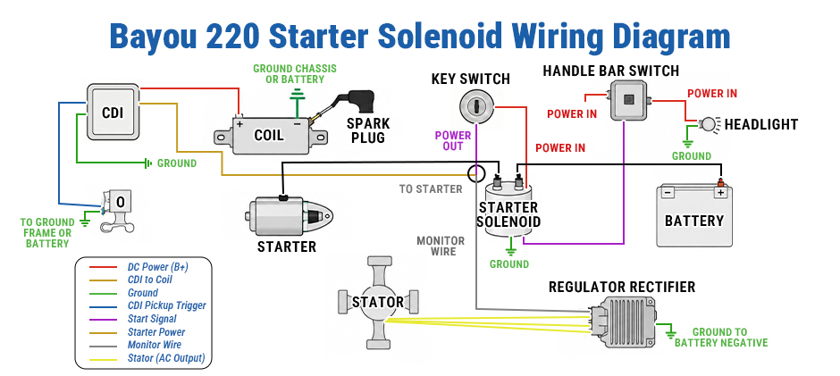
Bayou 220 Circuit Layout
On the Bayou 220, the starting system usually follows this path:
- The battery positive feeds the main fuse
- Fused power goes to the B terminal
- The M terminal sends power to the starter motor
- The S terminal gets the start signal from the switch circuit
- Ground returns through the chassis or a dedicated ground path
Bayou 220: What To Check
When using a Bayou 220 Kawasaki starter solenoid wiring diagram, these are the main items to verify:
- The battery feed cable is on the correct large stud
- The starter motor cable is on the other large stud
- The trigger wire is on the small terminal
- The fuse is installed and not open
- The ground point is clean and tight
Bayou 220 Common Issues
Older Bayou 220 machines often have harness problems that make wire color less reliable than wire function.
Watch for:
- Dirt-covered wire colors
- Previous repairs
- Loose ring terminals
- Corrosion at the fuse block
- Wrong relay connector position
A replacement starter relay fuse assembly or battery terminal end may also look different from the old part. That is why the terminal job matters more than the connector shape.
KZ550 Kawasaki Starter Solenoid Wiring Diagram
The KZ550 is a useful second case because the wiring is more compact. The routing is tighter than on an ATV, so the cable position can be harder to follow during repair. Even so, the logic in the Kawasaki starter solenoid wiring diagram stays the same.
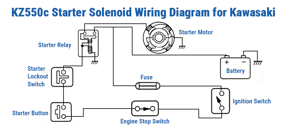
KZ550 Circuit Layout
On the KZ550, the basic start path is usually:
- Battery positive to the main fuse
- Main fuse to the B terminal
- Solenoid output from the M terminal to the starter motor
- Start signal from the handlebar switch to the S terminal
- Safety path through the relevant switch circuit
- Ground through the frame and engine
KZ550 What To Check
When reading a KZ550 Kawasaki starter solenoid wiring diagram, focus on these points:
- Tight harness routing near the frame
- Start switch signal reaching the relay
- Clean the battery and engine ground points
- Secure connection at the starter motor
- Correct relay terminal identification
KZ550 Common Issues
On older KZ550 machines, a no-crank fault may come from more than one small problem at the same time.
Typical causes include:
- Low battery voltage
- Dirty switch contacts
- Loose ground strap
- Corroded starter relay
- Weak connection at the starter motor terminal
A fresh starter solenoid, clean ground cable, or secure ignition switch connector can often solve issues that look larger than they really are. If the spark is weak or inconsistent, checking the ignition coil is also a practical step.
How To Identify Wires When The Diagram Is Missing?
A missing Kawasaki starter solenoid wiring diagram does not stop the job. The wires can often be identified by size, routing, and voltage behavior. This method is safer than guessing from the relay shape.
Step 1: Find The Battery Feed
Look for the heavy cable from the battery positive.
Signs include:
- Thick insulation
- Large ring terminal
- Routing from the battery area
- Path through or near the main fuse
This wire usually goes to B.
Step 2: Find The Starter Motor Cable
Trace the second heavy cable leaving the solenoid.
It usually:
- Runs toward the engine
- Ends at the starter motor post
- Uses a ring terminal similar to the battery cable
This wire usually goes to M.
Step 3: Find The Trigger Wire
Now locate the smaller control wire.
It usually:
- Comes from the start switch circuit
- Is much smaller than the main cables
- Shows voltage only during START
This wire usually goes to S.
Step 4: Confirm The Ground Path
A complete ground path is just as important as the power feed.
Check for:
- Clean frame ground
- Solid engine ground
- Tight mounting points
- No paint or rust-blocking contact
- Separate ground wire if the relay uses one
A poor ground strap or dirty chassis ground point can make a good relay act dead.
Step 5: Verify The Replacement Relay
Aftermarket relays do not always place terminals in the same physical position.
Before connecting power, check:
- Terminal letters
- Connector pin labels
- Fuse location
- Mounting direction
- Ring terminal fit
This is especially important when using a replacement starter solenoid, relay fuse block, or starter relay connector.
Step 6: Recheck Before Final Connection
Before reconnecting the battery, confirm the basics:
- Battery cable on B
- Starter cable on M
- Trigger wire on S
- Ground path complete
- Fuse installed correctly
- No loose cable touching the frame
Troubleshooting Tips Before Replacing Parts
It is easy to replace the relay too early. A few simple checks can save time.
If The Solenoid Clicks But Does Not Crank
Check:
- Battery voltage
- Main cable connections
- Starter motor cable
- Internal relay contact
- Starter motor itself
If The Solenoid Does Not Click
Check:
- Trigger wire voltage
- Start button
- Ignition switch
- Safety switches
- Ground path
Quick Symptom Table
| Symptom | Likely Area | First Check |
|---|---|---|
| No click, no crank | Control circuit | Trigger wire and switches |
| Click, no crank | High-current circuit | Battery and heavy cables |
| Intermittent crank | Loose connection | Cable ends and grounds |
| Fuse blows | Short circuit | Harness and terminal contact |
| Weak crank | Low voltage | Battery and starter cable |
These checks work well with a Kawasaki starter solenoid wiring diagram because they match the actual current path and signal path.
Final Words
The main value of a Kawasaki starter solenoid wiring diagram is that it helps turn a confusing harness into a few clear checks. Once each wire is matched to its job, both wiring and troubleshooting get easier. If parts need to be replaced along the way, FridayParts offers aftermarket options at affordable prices, with a wide inventory and fitment coverage for many types of equipment.
