

A faded fuse box label and a missing manual are two of the most common obstacles when diagnosing electrical problems on a Kubota. This guide gives you a practical reference for the L, M, BX, and RTV series, including fuse box location, layout style, fuse amperage, and protected circuits. It also covers faded labels, fuse replacement, repeated fuse failure, and how to add an auxiliary fuse panel safely.
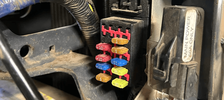
Quick Reference Table for Popular Kubota Series
The table below gives a fast comparison across several common Kubota series. This is especially useful when your exact model is not listed in a short forum post, but the panel style is similar.
| Series and Model | Fuse Box Location | Layout Type | Common Fuse Ratings | Typical Protected Circuits |
|---|---|---|---|---|
| Kubota L4600 | Near the operator area and steering support | Small numbered fuse panel plus larger separate fuses | 5A, 10A, 15A, 40A, 50A | Alternator, headlights, hazard, panel, work light, starter relay |
| Kubota M8540 Narrow Cabin | Cabin electrical area; location varies by configuration | Main panel plus high-amp fuse section | 5A to 100A | Defogger, 4WD, A/C, wiper, auxiliary power, key switch |
| Kubota BX25DLB | Under hood near the engine-side electrical cover | Compact fuse block plus one larger main fuse | 10A, 15A, 20A, 50A | Solenoid, ACC, hazard, working light, DC outlet |
| Kubota RTV900 | Under a protective cover in the service area | Standard fuse box plus slow-blow fuse box | 5A to 60A | Key switch, alternator, headlamp, fan motor, horn, 12V output |
This comparison also shows why Kubota fuse box diagram searches often lead to mixed results. Panel shape, cover style, fuse count, and circuit grouping can vary a lot between the L, M, BX, and RTV series.
Kubota Fuse Box Diagrams by Series
Below are series-specific examples organized by model. Each one focuses on the four details most owners need first: location, layout, amperage, and protected circuit.
L Series Example: Kubota L4600 Fuse Box Diagram
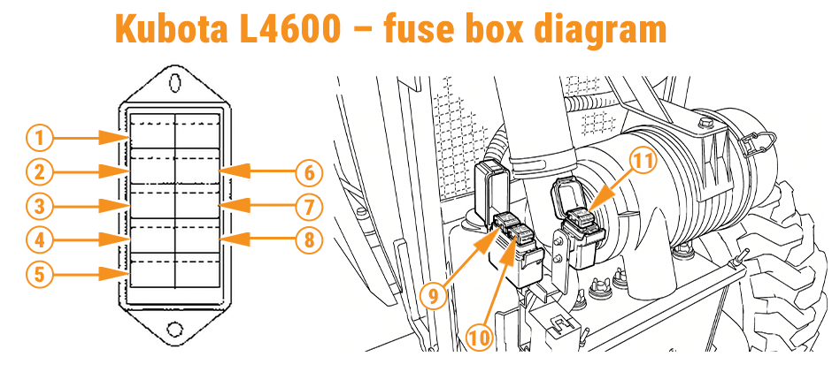
The Kubota L4600 uses a relatively simple panel layout, but it still helps to have the fuse list clearly organized.
L4600 Fuse List
| Number | Ampere Rating | Protected Circuit |
|---|---|---|
| 1 | 15A | Alternator |
| 2 | 5A | Head lights |
| 3 | 5A | Hazard |
| 4 | 15A | Panel |
| 5 | 5A | T/M Controller 1 |
| 6 | 5A | Work light |
| 7 | 10A | Brake lamp switch |
| 8 | 10A | T/M Controller 2 |
| 9 | 50A | Key stop |
| 10 | 40A | Starter relay |
| 11 | 40A | Dome lamp |
Location Notes
The fuse area is typically near the operator station and steering support. The smaller blade fuses are grouped together, while the larger fuses are placed nearby in a separate section.
What This Layout Tells You
- Lower-amp fuses usually protect signal and control functions
- Higher-amp fuses usually protect starting and key electrical circuits
- A panel like this is easier to read if the slot numbers are still visible
- If the label is worn, fuse count and fuse position become more important
M Series Example: Kubota M8540 Narrow Cabin Fuse Box Diagram
The layout below applies to the M8540 Narrow Cabin model. Fuse positions and circuit assignments may differ between Cabin and ROPS versions, so this should not be treated as a universal fuse diagram for every M8540 Narrow tractor.
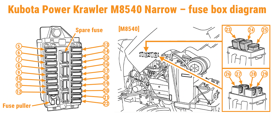
M8540 Narrow Cabin Main Fuse Panel
| Number | Ampere Rating | Protected Circuit |
|---|---|---|
| 1 | 20A | Side Window Defogger |
| 2 | 20A | Rear Window Defogger |
| 3 | 10A | 4WD or Bi-Speed Turn |
| 4 | 10A | 4WD brake |
| 5 | 15A | Work Light Rear |
| 6 | 15A | Work Light Front |
| 7 | 15A | Cigarette Lighter |
| 8 | 20A | Air Conditioner Fan Motor |
| 9 | 10A | Air Conditioner Compressor |
| 10 | 15A | Work Light Front Side |
| 11 | 15A | Auxiliary Power |
| 12 | 5A | Starter Relay |
| 13 | 5A | Radio |
| 14 | 5A | Air Conditioner Control |
| 15 | 15A | Wiper |
| 16 | 5A | Alternator, Engine, PTO, Heater |
| 17 | 5A | Meter Panel, OPC |
| 18 | 10A | Turn Signal, Stop Lamp |
| 19 | 10A | Meter, Radio Back Up |
| 20 | 20A | Headlight, Position Lamp |
| 21 | 20A | Flasher Hazard |
| 22 | 20A | Spare Fuse |
M8540 Narrow Cabin High-Amp Fuse Section
| Number | Ampere Rating | Protected Circuit |
|---|---|---|
| 23 | 50A | Headlight, Hazard |
| 24 | 50A | Air Heater |
| 25 | 100A | Charge |
| 26 | 30A | Electrical Outlet |
| 27 | 40A | Air Conditioner |
| 28 | 30A | Work Light, Fuel Cut Solenoid |
| 29 | 30A | Key Switch |
Why This Matters
This example shows why a Kubota fuse box diagram is not only about locating one blown fuse. On the M8540 Narrow Cabin, you may need to inspect both the main fuse panel and the separate high-amp fuse section.
It also helps with:
- Cab fuse identification
- Secondary fuse panel checks
- High-current circuit checks
- Accessory power tracing
- Charge circuit troubleshooting
BX Series Example: Kubota BX25DLB Fuse Box Diagram
The BX25DLB uses a smaller fuse panel, but the troubleshooting goal is the same: identify the location, match the fuse slot, confirm the amperage, and verify the protected circuit.
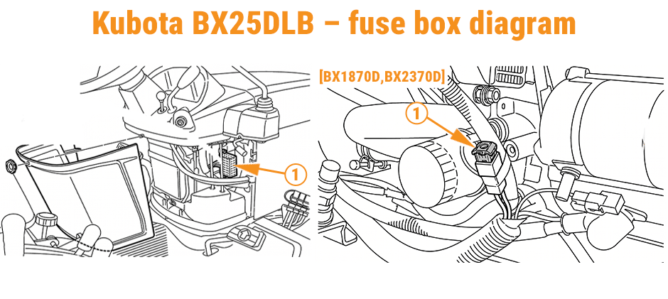
BX25DLB Main Fuse Box
| Number | Ampere Rating | Protected Circuit |
|---|---|---|
| 1 | 15A | Solenoid |
| 2 | 15A | Hazard |
| 3 | 15A | ACC |
| 4 | 20A | Working Light |
| 5 | 10A | DC Outlet |
| 6 | 10A | Timer Relay |
BX25DLB Separate Main Fuse
| Number | Ampere Rating | Protected Circuit |
|---|---|---|
| 1 | 50A | Check circuit against wrong battery connection |
Location Notes
The BX fuse box is usually under the hood near the engine-side electrical area. The smaller fuse block and the larger main fuse are separate, so both should be checked during diagnosis.
This kind of compact setup is common on smaller tractors, which makes regular inspection of battery connections, DC outlet wiring, and solenoid-related circuits more important than many owners expect.
RTV Series Example: Kubota RTV900 Fuse Box Diagram
The RTV900 adds an important detail that many quick guides skip: some Kubota machines use both standard blade fuses and slow-blow fuses.
RTV900 Fuse List
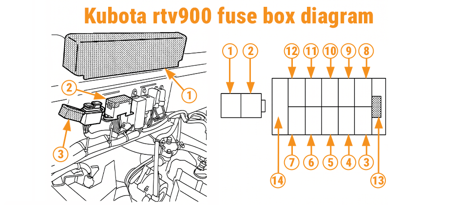
| Fuse No. | Capacity | Protected Circuit |
|---|---|---|
| 1 | 50A slow-blow | Key switch |
| 2 | 60A slow-blow | Alternator |
| 3 | 15A | Head lamp, Tail lamp, Panel |
| 4 | 5A | Glow lamp |
| 5 | 10A | Hazard |
| 6 | 20A | Fan motor |
| 7 | 15A | Engine stop |
| 8 | 15A | Alternator, Brake lamp, Fan motor relay |
| 9 | 5A | Panel, Engine stop control |
| 10 | 10A | 12V DC output |
| 11 | 10A | Horn |
| 12 | 15A | Work light |
| 13 | — | Fuse puller |
| 14 | Spare | 5A, 10A, 15A, 20A |
Service Tip
Standard blade fuses and slow-blow fuses are not interchangeable. Always match both the type and the rating before replacement.
How to Replace a Kubota Fuse?
Once you identify the correct Kubota fuse box diagram, replacement is usually straightforward.
Basic Steps
- Park the machine safely and shut it off
- Remove the key
- Open the fuse box cover
- Check the slot number and fuse amperage
- Pull the fuse with a fuse puller
- Inspect the metal strip or test with a multimeter
- Replace it with the same rating only
- Test the protected circuit
Keeping assorted blade fuses and a fuse puller in the toolbox can make field repairs much easier.
Four Ways to Deal with a Faded Fuse Label
A faded label is a very common problem. Many owners can find the panel, but cannot read the fuse map. That makes a good Kubota fuse box diagram even more valuable.
1. Match the Panel Shape and Slot Count
Compare the actual panel to a manual, service image, or saved reference photo. Focus on:
- Total number of slots
- Left and right arrangement
- Spare fuse position
- Larger main fuse position
2. Use Fuse Color as a Clue
Fuse color can help identify 5A, 10A, 15A, or 20A circuits. But color alone is not enough, because several different circuits may use the same amperage.
3. Work Back from the Failed Function
If the failed function is obvious, start there. For example:
- No headlights
- No hazard lights
- No radio
- No A/C fan
- No work light
- No 12V output
Then match that symptom to the protected circuit list.
4. Make a New Label Before the Next Failure
A little preparation now can save a lot of time later:
- Print a small chart
- Write the slot map in a service log
- Add a weather-resistant label
- Keep a marked photo on your phone
When a Fuse Keeps Blowing
A fuse that fails repeatedly usually points to a circuit problem, not just a bad fuse.
Start With These Checks
- Confirm the correct amperage
- Confirm the protected circuit
- Inspect the wire harness
- Check switches, lamps, motors, or outlets on that circuit
- Look for water, heat damage, or rubbed insulation
- Test with a multimeter
Common Causes
- Short circuit
- Damaged wire harness
- Failed relay
- Overloaded accessory
- Corroded connector
- Faulty motor or solenoid
- Poor add-on wiring
Many people search for a Kubota fuse box diagram when the real fault is deeper in the electrical system. The blown fuse is often only the visible symptom.
How to Add an Auxiliary Fuse Panel Safely?
Extra lights, monitors, chargers, and sprayer controls often need their own circuit protection. In those cases, an auxiliary fuse panel is usually safer than tapping into a small factory circuit.
Best Practice for Add-On Circuits
- Use a dedicated power feed
- Add an inline main fuse
- Use a relay for switched power
- Route the harness away from heat and sharp edges
- Label each new circuit clearly
Good Uses for an Added Fuse Box
- LED work lights
- USB charger
- Extra 12V outlet
- Sprayer controls
Final Words
The right Kubota fuse box diagram helps you locate the panel, understand the layout, verify fuse amperage, and match each slot to its protected circuit. It also makes faded labels, fuse replacement, and electrical troubleshooting much easier. If replacement parts are needed, FridayParts is a trusted aftermarket parts supplier with high-quality products at affordable prices, a large inventory, and wide compatibility across many heavy equipment brands.
