

For a tractor drawbar, the hitch pin diameter depends on the category — 38 mm on Cat 3, 50 mm on Cat 4, 70 mm on Cat 5. Torque Specs follow the same logic: 430 N·m on the support mounts and 610 to 750 N·m on the hammerstrap bolts. The rest of this guide covers what the numbers don’t tell you: load limits at each drawbar position, PTO shaft geometry, height clearance, and the wear points worth checking before spring.
Pin Diameter and Torque at a Glance
Before hooking up an implement, match the pin, the hitch link, and the torque spec to the drawbar category. Mixing sizes is the fastest way to bend a pin or crack a link.
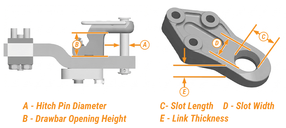
| Category | Hitch Pin Diameter | Drawbar Opening Height | Slot Width (min.) | Link Thickness |
|---|---|---|---|---|
| 3 | 38 mm (1.5 in) | 70–90 mm (2.75–3.54 in) | 41 mm (1.61 in) | 48 mm (1.89 in) |
| 4 | 50 mm (1.97 in) | 90 mm (3.54 in) | 55 mm (2.17 in) | 50 mm (1.97 in) |
| 5 | 70 mm (2.75 in) | 100 mm (3.94 in) | 73 mm (2.87 in) | 60 mm (2.36 in) |
A Category 4 hitch link will only fit a Category 3 drawbar if the opening height reaches 90 mm (3.54 in). Below that, the pin sits crooked and the contact area is reduced.
Hitch Pin Diameter by Category
Hitch pin diameter is the single most important spec when pairing a drawbar with an implement. An undersized pin shears under load. An oversized pin will not seat in the slot, and forcing it wears the link bore oval.
Category 3, 4, and 5 Sizing
- Category 3: 38 mm (1.5 in) pin. Common on tractors in the 150–250 PTO hp range.
- Category 4: 50–51 mm (1.97–2.0 in) pin. Used on high-horsepower row-crop and articulated tractors.
- Category 5: 70 mm (2.75 in) pin. Reserved for the largest 4WD tractors and heavy tillage or scraper pans.
If your tractor came with a Category 5 drawbar but the implement uses a Category 4 hitch link, the right fix is an adapter kit. Don’t grind, weld, or shim a pin to make it fit. Improperly sized hitch combinations wear out drawbar components fast and can fail under load.
When to Step Up to a Category 5 Pin
Use the Category 5 pin whenever the implement produces:
- More than 348 kW (467 hp) engine power, or
- More than 300 kW (400 hp) at the PTO.
Below those numbers, a properly rated Category 4 setup is usually enough. Talk to the implement maker before converting so the hitch link is approved for the larger pin. Category 3 and Category 4 draw pin diameters, for reference, are 38 mm (1.5 in) and 51 mm (2.0 in), respectively.
Torque Specs for Tractor Drawbar Hardware
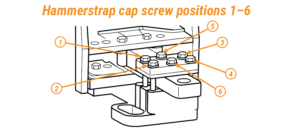
Torque specs matter as much as pin sizing. Loose cap screws let the drawbar shift under load, and shifted hardware chews mounting holes fast. Use a calibrated torque wrench and a crisscross tightening pattern every time.
Heavy-Duty Drawbar Cap Screw Torque
| Fastener | Torque |
|---|---|
| Support cap screws (single-position drawbar) | 430 N·m (318 lb-ft) |
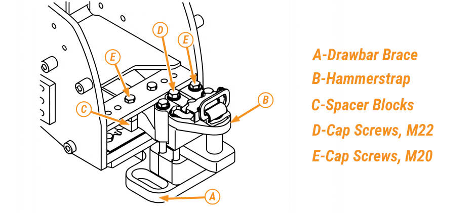
| Hammerstrap cap screws 1–4 (M22) | 610 N·m (450 lb-ft) |
| Hammerstrap cap screws 5–6 (M20) | 750 N·m (553 lb-ft) |
Special cap screws are used on drawbars, so any replacement fastener must match the original grade. Standard grade 5 bolts will stretch and lose clamp load in this application. A quality replacement screw comes heat-treated to the correct spec.
Tightening Sequence
Torque in a crisscross pattern so the plate seats flat:
- Snug every fastener hand-tight.
- First pass at 50% of final torque.
- Second pass at 75%.
- Final pass at full spec.
- Recheck torque after the first heavy pull.
New drawbar mounts settle after their first working day. A quick retorque prevents loose hardware, elongated bolt holes, and the drift that grinds a hammerstrap out of true.
Matching Load Limits to PTO and Position
Static vertical load is the weight the implement pushes down on the drawbar pin at rest. Push past the number and the drawbar bends, the pin bore wears oval, or the frame cracks near the support. Rough terrain and speed multiply that load quickly.
Load Limits by Drawbar Position
Long drawbar extensions cut the safe vertical load because the lever arm grows. The short position handles more weight.
| Setup | Drawbar Position | Max Static Vertical Load |
|---|---|---|
| Cat 4 drawbar, long (508 mm / 20 in) | Rear hole | 2,268 kg (5,000 lb) |
| Cat 4 drawbar, short (358 mm / 14 in) | Front hole | 2,470 kg (5,450 lb) |
| Cat 4 with reinforcement kit, long | Rear hole | 4,082 kg (9,000 lb) |
| Cat 4 with reinforcement kit, short | Front hole | 4,990 kg (11,000 lb) |
| Cat 5 with 3-point hitch | Single position | 4,580 kg (10,100 lb) |
| Cat 5 with drawbar support | Single position | 5,440 kg (12,000 lb) |
Once vertical load passes about 2,043 kg (4,500 lb) on a standard Category 4 drawbar, the heavy-duty drawbar support belongs on the tractor. On smaller frames, the trigger point drops to 2,245 kg (4,950 lb). The kit adds a brace, hammerstrap, spacer blocks, and M22 and M20 cap screws that carry the extra load into the frame.
PTO Shaft Distance and Draw Pin
Distance from the PTO shaft end to the draw pin hole controls implement driveline geometry. Get it wrong, and the shaft binds at full articulation.
- 540 rpm PTO, 44 mm shaft: 356 mm (14 in) shaft end to pin
- 1000 rpm PTO, 44 mm shaft: 406 mm (16 in) shaft end to pin
- 1000 rpm PTO, 35 mm shaft with adapter: 400 mm (16 in) from adapter end
If a shaft adapter reduces a 44 mm (1-3/4 in) driveshaft to 35 mm (1-3/8 in), measure from the end of the adapter, not the original shaft. Sloppy measurement here is a leading cause of driveline damage on heavy tillage.
Adjusting Clearance and Avoiding Damage
Drawbar height sits between two limits. Too low and the tongue drags implements poorly. Too high and the PTO shaft can strike the hitch strap during articulation.
Powerline Clearance
Keep a minimum of 76 to 89 mm (3 to 3.5 in) between the powerline and the top of the hitch strap, measured on level ground. Anything less risks driveline damage when the front of the tractor noses down over a rise.
Signs Drawbar Height Is Wrong
Too low, on hay work:
- Windrows drag under the pickup
- Feed opening closes and feeding capacity drops
- Pickup float goes flat at spring settings
- Bale discharge slows
Too high:
- Pickup teeth miss the ground
- Gate will not clear the bale on discharge
To raise the drawbar, flip it so the offset points up. On a standard rear-mount setup, remove the locking pins, slide the bar to center, reinstall the locking pins, and pull the clevis assembly if fitted. Check every mating surface for burrs before it goes back together, since a burr under the locking pin is enough to shift the bar under pull.
Pre-Season Inspection Points
Run through this checklist before heavy pulling starts:
- Look at the pin bore for elongation or hairline cracks. For related components, check the bearing, gear, and shaft category before ordering.
- Check the hitch link slot width against the category dimensions.
- Confirm the pin diameter matches the category.
- Retorque cap screws to the values in the table.
- Grease locking pin sleeves and the swinging drawbar pivot.
- Verify powerline clearance at full articulation.
A worn hitch link or stretched pin bore is cheap to swap and dangerous to leave in service. Quality aftermarket drawbar parts in the correct category and grade restore the original ratings without a long dealer wait.
Final Words
Correct pin size, correct torque, and correct load limit are what keep a tractor drawbar working season after season. Match the category, follow the tightening sequence, and respect the vertical load numbers for your position and PTO combination. When it is time to replace a pin, hitch link, cap screw, or heavy-duty support, we at FridayParts stock aftermarket drawbar parts at fair prices with broad fitment across heavy equipment brands, so you can get the machine back in the field.
